|
|
|
|
|
|
|
|
|
|
|
|
|
|
|
|
|
|
Air of Authority - A History of RAF Organisation
|
|
|
|
|
|
|
|
|
|
|
|
|
|
|
|
|
|
Ground Radar Developments (WW2)
Early Developments
The earliest plan to use radio waves to locate objects was proposed in a patent of 1904 by a German, Christian Hulsmayer, which he called a 'Telemobiloscope and was intended to be used by ships to detect other ships in fog. However at the time the means of amplifying the radio waves did not exist. Over the next thirty years the necessary element began to come together, the diode valve was invented in 1904 by Professor Ambrose Fleming with the triode valve following in 1907, allowing the amplification of radio signals. In 1925 two Americans used pulsed radio waves to ascertain the altitude of the layer of ioned gas around the earth and in 1929 Professor Yagi in Japan published his theories of using directional aerials to transmit and receive narrow radio beams. The major elements needed for the development were now in place.
In Germany in 1933 Dr Rudolph Kuhnold of the German Navy's Research Department was working on what is now called Sonar for detecting objects under water with sound waves and thought the same principle could be applied to the air using radio waves and developed a small prototype radar set but it was so underpowered to be useless. However by the end of 1933 Philips in Holland had produced a valve capable of generating 70 Watts at 600 Megahertz and his new design was put into production in January 1934. With the frequency reduced to 125MH, by the end of 1936 this radar, named 'Freya' was capable of detecting aircraft at 50 miles.
In Britain, an initial investigation into the use of radio waves to used as a form of 'death ray' to make aircraft engines cut out proved unworkable but the scientist, Robert Watson-Watt, given the task decided that they could be used to locate enemy aircraft rather than destroy them and set about developing a workable system in 1935. In typical British style the first experiments were carried out using the BBC's transmitters at Daventry rather than a specially built prototype unit. By 1937 construction of a number of RDF (codename - Radio Direction Finding) station around the coast of Britain had begun. Whilst in many ways inferior to German radar developments at the time, the British system was superior in an organisational sense and it was this aspect that proved so successful during the Battle of Britain in 1940.
Another name which should always be associated with these
developments in Britain is Hugh Dowding.
In 1929 he became Air Officer Commanding, Fighting Area,
and as a result was in command of all fighters in the UK
Chain Home (AMES Type 1 & 9)
The first RDF units set up was code named Air Ministry Experimental Stations Type 1 of more simply 'Chain Home' (CH) with the first being built at Bawdsey in Suffolk and by August 1939 nineteen of them provided coverage of the South and East coasts of the UK from the Isle of Wight to the Hebrides. These stations operated on a wavelength of 12m which necessitated very long aerial arrays which where hung between four (and later on some stations, three) 360 ft high steel towers, with a further four 240 ft tall wooden receiver towers. As stations began to be built westwards, they adopted two 325 ft steel masts guyed for stability to hold the aerial arrays whilst two wooden towers, similar to those on the East Coast where used for receiving. The CH stations were only able to provide an indication of aircraft approaching the UK from across the sea but not overland, this was remedied by the CHL and GCI systems. Type 9 was a mobile CH consisting of 105 ft telescopic masts which was used both overseas and as a temporary measure in the UK during the construction or repair of normal CH stations, the units which operated Type 9s were usually known as Mobile/Transportable Radio Units. [UK Chain Home Stations]
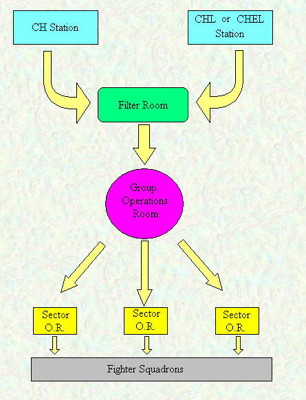
The diagram above shows the sequence through which information flows from the detecting station to the 'scrambling' of the operational fight squadrons.
Filter Room - Data from the RDF stations was fed to the Filter Room were it was combined with other information to determine which plots were hostile and which were friendly.
Group Operations Room - Here markings showing the strength and tracks of hostile targets would be placed on a large scale map of the area coverings, allowing controllers to ascertain likely targets.
Observer Corps - In the CH system, once enemy aircraft had crossed the coast and were heading inland, they could no longer be tracked by the RDF system and so reports from the civilian manned Observer Corps were needed to maintain the plot.
Sector Operations Room - Each Sector consisted of a Sector airfield and a number of satellites with fighter squadrons based on them. The Controller in the SOR had to decide which units or parts of units to 'scramble' an to direct the fighters onto the hostile aircraft, hopefully in an advantageous position to effect an interception.
Chain Home/Overseas Low (AMES Type 2 & 5)
The major problem with the original CH system was that its low frequency and long wave length made it almost impossible to detect aircraft flying at low level from the 'ground clutter'. The Army section at the Bawdsey Research Station had been working on this problem and produced a system that operated on a 1.5m wavelength, the resulting RAF system being known as Chain Home Low (CHL) It was early 1940 before the first CHL units were set up alongside existing CH stations. Because of the reduced wavelength there aerial was also greatly reduced and it was now possible to build a unit in which the antenna could be rotated, first by hand and later powered, this now meant that the whole airspace around the station could be searched not just the area in front of it. A version of CHL was developed for use overseas known as Chain Overseas Low (COL) and AMES Type 5. [UK Chain Home Low Stations]
Chain Home Extra Low (AMES Types 14, 52, 53, 54(a), 54(b), 55, 56, & 57)
Probably the biggest breakthrough in the design of radar sets was the Cavity Magnetron, which permitted the generation of high power outputs at at wavelengths of 10cm or less, these radars being known as 'Centimetric'. Here the Admiralty were first to develop ground based sets using this technology but the RAF quickly adopted the Naval Type 271 and Type 277 set for their own purposes. The high powers and short wavelengths improved the low level detection ability of these systems dramatically. However both CHL and CHEL where located on the coast often alongside CH and despite their ability of see all around their positions often excluded them from being used to track hostile aircraft very far inland. The Type 11 was a mobile version of CHL operating on 50cm wavelength for use in an emergency should the standard 1.5m set suffer jamming, 50cm being the wavelength used by the Germans, so less likely to be jammed in case they effected their own systems. Similar to the Type 14 was the Type 13 'Nodding' heightfinder, which utilised the same electronics but scanned in the vertical plain rather then the horizontal. All the types listed below were based on the Naval Type 277: -
Type 52 - utilised a circular, parabolic dish type antenna located on a gantry above the Transmitter/Receiver Hut
Type 53 - similar to Type 52 but utilising a horizontal 'cheese' antenna.
Type 54(a) - utilised a circular dish mounted on a 200 ft tower with the transmitter being located just below the dish.
Type 54(b) - same as Type 54(a) but with the transmitter being located at the base of the tower.
Type 55 - this was a circular dish mounted at the 200 ft point of a 360 ft CH mast with the transmitter in a hut at the base.
Type 56 - utilised a circular dish antenna at the top of a 185 ft wooden tower with the transmitter at the base in a Nissen hut.
Type 57 - this was a fully mobile unit with a horizontal 'cheese' antenna mounted on a trailer containing the transmitter and receiver.
[UK Chain Home Extra Low Stations]
Ground Controlled Interception (AMES Type 7, 8, 15, 16)
Once an intruder had crossed the coast and was overland a means was needed to maintain track of the intruder and preferably to direct an interceptor onto the target. This was achieved by taking the principal of the CHL set but adding the ability to quickly determine the height of a target. The latter was achieved by splitting the vertical axis of the antenna into section so that the strengths of returns to each section could be used give a height reading. This combined with the Plan Position Indicator (PPI) meant that the bearing and range could be read from the same screen with a height screen situated next to it. With GCI stations situated in the country and each working with fighter units allocated to its control the controller was able to see the position and height the target and of the interceptor in relation to it at the same time, enabling him to 'vector' the interceptor into position so that it could 'see' the target either visually or on its own Airborne Interception (AI) radar. Type 7 was also known as the 'Happidrome', which actually superseded the Type 8 and Type 15 was a mobile version of Type 7. GCI radars were also known as Chain Home Beam (CHB) [UK Ground Controlled Interception Stations]
Other Types
Type 3 - This was the designation given to a station with a CH and CHL working in close proximity.
Type 4 - Overseas Chain (CO), also known as Intermediate Chain Home (ICH)
Type 6 - Early Light Warning Set, converted from Anti-Surface Vessel (ASV) sets. They were used to give early warning to the 3GHz Gun Control Radar, usually housed in tents and fully transportable and mobile.
Type 10 - Advance Chain Overseas (ACO). This was a version of Type 9 in both static and mobile versions, utilising 125 ft towers.
Type 11 - This was a mobile CHL/GCI set.
Type 12 - This was a transportable CHL/COL set working on 125 MHz in the Mk 1 version. The Mk 2 was also known as 'Red Queen' and operated in the 192-209 MHz range.
Type 16 - These were Fighter Direction Stations, with four in the UK and one in Malta. The original concept was for them to control fighter sweeps over France.
Type 17 - A Fighter Direction Station similar to Type 16 but operating on different frequencies, this type was abandoned.
Type 18 - This was a modified Type 11 with height finding capability but was abandoned.
Type 19 - This was a standby GCI set.
Type 20 - This was a height finding set based on the Type 16
Type 21 - This was a convoy comprising of five vehicles, carrying a Type 13, a Type 14, a control centre and two diesel generators.
Type 22 - Similar to Type 21 but with Type 11 instead of the Type 14.
Type 23 - see LORAN
Type 24 - Long range height finding set for use with Type 16 and MEW stations.
Type 25 - This was an experimental CHL convoy incorporating Types 11, 13, 14 and 15.
Type 26 - This operated at 3 GHz and was a British version of the American MEW using two Type 14s.
Type 27 - This was an air transportable GCI operating at 3.35 GHz.
Type 28 - This was an air transportable height finder similar to the Type 13 for use in conjunction with a Type 27 (known as CMH).
Type 29 - This was an air transportable CHEL set but was abandoned.
Types 30-37 - These were low power versions of the Naval 10cm NT271 sets, used for coast watching.
Types 40-47 - These were medium power versions of the Naval 10cm NT271 sets, used for coast watching.
VEB - This was a a height finder using a vertical stack of 56 dipoles to create a vertical fan beam moved electronically rather the physically.
LORAN (AMES Type 700)
To be added
Type 23 - LOMAN
GEE (AMES Type 7000)
To be added
OBOE (AMES Type 9000)
To be added
GEE-H
To be added
This page was last updated on 17/10/23©